One of the most important aspects of the success of the PVRES home, is the ability to take advantage of all the features designed to reduce cooling loads. We used RHVAC (Elite Software) to calculate the machine size for both the standard home and the control home in Lakeland, Florida. RHVAC uses Manual J for its calculations. We entered all of the building features for either house in detail (walls, roof, glass, duct system etc.), but as a conservatism we chose an 95°F outdoor design temperature rather than the 91°F, suggested by Manual J along with a 75°F interior temperature.
The Manual J calculations suggested a cooling system of 3.88 tons for the standard home (4 tons) and 1.73 ton (2 tons) for the PVRES house. Although, the two ton system for such a large home (2,400 square feet) is highly unusual, Tim Rice of Ward’s Air Conditioning in Lakeland has worked with FSEC and with Keith Ledford and John Price out of the Orlando and Tampa Trane offices to come up with a suitable system. In a related project, we have had a very good experience with Trane’s XL 1400 series air conditioner.
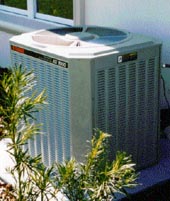
Consequently, we were able to select the TWY024A two-ton heat pump for the project. We will use the TWE040E13 variable speed indoor air handler to provide optimum efficiency, humidity removal and quiet operation. The Seasonal Energy Efficiency Ratio (SEER) of the combination is 14.4 Btu/W; the analogous Heating Season Performance Factor (HSPF) is 8.5 Btu/W. For the standard home we will use a standard efficiency 4-ton Trane heat pump– a TWR048C (SEER= 10.0 Btu/W; HSPF= 7.0) as shown in the bottom right photograph.
Air Conditioner Performance Testing
After each air conditioner was successfully installed by the contractor (Ward’s Air Conditioning in Lakeland), we performed one-time tests to establish the relative performance of the two units. As described by the section on the air conditioning system, we used Trane heat pumps for both air conditioning systems. Based on Manual J sizing, we installed a four ton (48,000 Btu) cooling system (Trane TWR048C with TWE42C14 air handler) at the Control home and a two ton system (TWY024A with a TWE040E13 air handler) (24,000 Btu/hr) in the PVRES home.
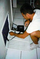
To perform the tests, we developed a procedure that can be used to measure the instantaneous efficiency of a cooling system. The procedure is entirely based on physical measurements. First the dry coil air flow is determined by turning on the heat pump back-up resistance heat elements and measuring the temperature rise across the heating coil. We used a portable Cooper Instrument Corp. (Middlefield, CT) SH66A multi-probe digital thermometer to take this measurement. By simultaneously measuring the element wattage (we turned off all non-AC breakers and measured this using the utility meter), the air flow cfm can be gauged through knowledge of air’s specific heat and density. As a check, we used a Shortridge flow hood to verify the estimate obtained by the resistance heat method (one hint for anyone doing this: make sure that the thermometer after the coil is around the first bend in the duct work, or at the first register, or you will risk poorly mixed air in the air stream after the coil).
Secondly, the air conditioner is turned on to cooling and the temperature drop across the coil is measured. Within the tests, we used two temperature probes before and after the coil. One set of the probes recorded the dry bulb temperature. During cooling operation, the other two probes had saturated cotton shoe-laces inserted into the air stream to measure the wet bulb temperatures before and after the coil. This would allow determination of the coil latent performance by looking at the change in enthalpy across the evaporator coil. As a check on this measurement, we also collected air conditioner condensate over a ten minute period once flow had begun. Finally, an outdoor temperature is taken at the condenser inlet since the rated EER of units is typically based on this condition and that indoors. The entire procedure is described below in the audit instructions, as well as an automated procedure for calculation.
The product of the change in enthalpy across the evaporator coil times the measured air flow yields the total cooling. By measuring the power demand of the AC system, the system energy efficiency ratio (EER) is obtained.
The measured air flow for the four ton heat pump was 1555 cfm or about 390 cfm/ton. This is well within the tolerance established for the air conditioner (400 cfm/ton). A 16.5 degree temperature drop was measured across the coil (Treturn = 69.2°; Tsupply = 52.7°; Treturn,wet = 50.8°; Tsupply, wet = 59.4°). The measured sensible cooling capacity of the unit at a 77.4 degree outdoor temperature was 26,680 Btu/hr; the latent cooling capacity was 8,560 Btu/hr for a total capacity of about 35,240 Btu/hr. With a 4,181 Watt power draw; this works out to an EER of 8.4 Btu/W. This is short the nominal SEER of 10 Btu/W, but the indoor temperature was much lower (69.2°F) than the 80 assumed in the ARI test procedure.
The test at the PVRES home was done with the variable speed air handler (VSAH) operating at full speed. The unit was configured with the VSAH operating such that much of the time it operates at less than half speed. (For each cooling cycle, the unit operates at 50% flow for the first minute, then 80% flow for the next 7.5 minutes and finally 100% after that if necessary). Our experience so far shows that the unit seldom operates at full speed since measured on cycles last about six minutes.) Still we wanted to evaluate the unit operating at maximum speed where sensible heat gain would be at its highest and latent heat removal at its worst (a notorious problem in Central Florida). Readers may recall that we designed the duct system to have low resistance to flow. At full speed, we measured an air flow of 1380 cfm. The unit was operated in this mode for 20 minutes before measurements were taken; the outdoor inlet air temperature was 87°F.
A 12.9 degree temperature drop was measured across the coil (Treturn = 70° [62° W.B.], Tsupply =57.1° [56° W.B.]) with a sensible cooling rate of 18,530 Btu/hr. Even at the high flow rate, latent performance was quite good with 8,770 Btu/hr of moisture removed. Total capacity was 27,300 Btu/hr with measured power at 2074 Watts– an overall EER of 13.2 Btu/W. The nominal SEER of the specific unit is 14.5 Btu/W. The rated capacity of the unit at the closest rated condition (85oF outdoor dry bulb, 72°F entering dry bulb, 63°F wet bulb) was 25,200 Btu at 900 cfm with an EER of 14.1 Btu/W. Given the higher outdoor temperature, the unit was very close to its rated efficiency.
Air Conditioning System Performance Audit Instructions
Draft February 16, 1998Depending on weather conditions it might be advantageous to modify the order of the 3 tests that comprise this audit (Fan Power, Dry Coil Air Flow, and Air Conditioning Performance). If the weather is such that the air conditioner has been cooling, the coil is likely to be wet and the condensate pan full. If this is the case, then task III (“Evaluate Air Conditioning Performance”) should be performed first, followed by tasks I and II.
I. Evaluate Fan Power (No heating or cooling)1) Turn system fan to “On” at the thermostat. Prepare small holes in the duct system, before and after the evaporator coil, being careful to avoid a location just above the coil which will allow the temperature probe to “see” the heat elements. Insert digital thermometer probes into center of air flow stream. Read values; the supply temperature should be higher than the return temperature because of fan heat. If Tsupply is less than Treturn, the coil is still wet. Wait five minutes after Tsupply is greater than Treturn and is stable over a minute (typically it will be 0.2 to 1.5oF or higher). If the coil is wet initially, it will often take 20 minutes to dry totally. Record return/ supply temperature difference [D].
2) While the fan is running, record the site, AC manufacturer and model data and obtain the utility meter Kh; it will usually be 7.2 Wh/rev; some units may be 3.6. Place exterior temperature probe at the inlet to the condenser coil. Avoid placing the probe in direct sun.
3) After 5 minutes perform Test#I. Inform the occupants that the indoor power will be off for a period of about one hour to complete the tests. Turn off all household breakers except for the air handler to insure that the only power draw is from the air handler fan. Go back to the utility meter and using a digital stop watch, start timing when the black band passes to the front of the meter and stop when it reaches this position again. Record the number of revolutions [A], and the elapsed seconds [B]. Then calculate the fan power [C]. It should typically be 200 – 600 W.
II. Evaluate Dry Coil Air Flow (Heating) Caution: For heat pumps, turn system off and wait several minutes before switching to heating mode if in cooling mode.1) Turn the system to heating mode at the thermostat if the unit has strip heaters; if it is a heat pump it must be turned onto “emergency heat” so that only the strip heat is activated. Set the thermostat to the highest value; noting the original setting so it can be returned to this point at the end of the test. If it is a gas furnace, flow can only be obtained by using a flow hood; the heating system cannot be used to obtain flow. Allow the system to run for five minutes to come into equilibrium. The strip heat can be confirmed to be “on” if the condenser is not running (confirmed by visual inspection) and if the power meter is moving quicker than it would be if only the air handler was running.
2) After five minutes, record the dry bulb temperatures before and after the coil. Then, with the stop watch, record the seconds [F] requires for ten revolutions [E] of the power meter.
3) Estimate dry coil air flow [G]. It should be approximately 350 – 425 cfm/ton (12000 Btu/h) although many units may show lower values.
4) Turn the heating system off at the thermostat.
III. Evaluate Air conditioning Performance (Cooling) Caution: For heat pumps, turn system off and wait several minutes before switching to cooling mode if in heating mode.1) Put the unit in cooling mode, and turn the thermostat down to its lowest setting. Allow the cooling system to operate for approximately 20 minutes until condensate flows at a consistent rate from the unit. Be sure to create a condensate “trap” to assure steady flow in the condensate drip. Set a timer and collect condensate for exactly ten minutes into a convenient vessel. Carefully pour contents into graduated cylinder and record milliliters of condensate water collected [M].
2) While condensate is being collected, use the stop watch to measure the time [K] required for 10 revolutions [J] of the utility meter.
3) Record the dry bulb temperature before and after the cooling coil and their difference [N].
4) Wet the cotton bulb over the two wet bulb temperature probes and insert in the return and supply air streams being careful that the wetted cover remains over the probe during the test. Wait five minutes and record values. Also record the outside air temperature at the condenser on the worksheet.
5) Compute power [L], sensible [O], latent heat [P] and system performance (EER) [R,S].
6) Note any unusual findings from the audit: (e.g. a gurgling sound during cooling operation; no condensate produced etc.). Turn the household breakers back on and reset the thermostat to the original setting.
7) Seal all holes made in the duct system; clean up all tools and return all things altered to their original condition. Thank the occupants for their cooperation before leaving.
Space Conditioning System Performance Audit
Site ID_____________________ Technician _____________________________ Date/Time_____________ Address____________________________________________________ Utility meter Kh: ________________ Nameplate Information Unit Type _________________________________ (Heat pump, AC or furnace)| Unit | Manufacturer | Model | Capacity (Btu/h) | SEER (Btu/W) |
| Outdoor | ||||
| Indoor unit (if split) |
| A | B | C | D | Original thermostat setting °F |
| Revolution | Time | Power (W) | T (oF) | |
| Number | Seconds | A * kh * 3600 / B | Tsupply – Treturn | |
| E | F | G | H | I | Tsupply °FTreturn °F |
| Revolution | Time | Power (W) | T (oF) | Air Flow (cfm) | |
| Number | Seconds | E * Kh * 3600 / F | Tsupply – Treturn | G * 3.27 / H | |
| J | K | L | M | N | Dry Bulb Wet Bulb Tsupply °F °F Treturn °F °F |
| Revolution | Time | Power (W) | Condensate | T (oF) | |
| Number | Seconds | J * Kh * 3600 / K | Milliliters in 10 min. | Tsupply – Treturn | |
| O | P | Q | R | S | Outdoor temperature by condenser inlet ______ F |
| Sensible Cooling (Btu/hr) | Latent Cooling (Btu/hr) | Total Cooling (Btu/hr) | EERTotal (Btu/w) | EERSensible (Btu/w) | |
| N * I | M * 14.04 | O + P | Q / L | O / L |
Space Conditioning System Performance Audit
| Green Values are entered | Red Values are Computed |